About LCD structure
LCDs come from the first letter of the word liquid crystal display. It is a passive display component, which means that they do not emit light and only use ambient light from the environment. By manipulating this light, very little energy is required. This makes LCDs the technology of choice for low power consumption.
We all know that LCDs use fields, but how does it work and what is the internal structure?
The display module consists of a display panel and a driver section.
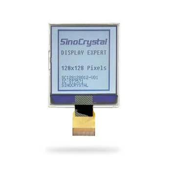
This is the basic structure of a monochrome display panel.
The liquid crystal box consists of a thin layer (about 3~7um) of liquid crystal sand sandwiched between two glass substrates with transparent electrodes deposited on its inner surface. Because the liquid crystal layer is liquid, it cannot withstand pressure, so there are some spacers between the two glass substrates.

Liquid crystal is the key material for liquid crystal display.

For twisted nematic liquid crystal displays, the two surfaces π are topographically orthogonal to each other, forming a 90 degree twist from one surface to the other.

This helical structure has the ability to control light. A polarizer is used at the front of the cell and an analyzer/reflector at the back of the cell. As randomly polarized light passes through the front polarizer, it becomes linearly polarized. It then passes through the front glass, is rotated by the liquid crystal molecules, and passes through the back glass. If the analyzer is rotated 90 degrees to the polarizer, the light will pass through the analyzer and be reflected back through the cell. The observer will see the background of the display, in this case the silvery gray of the reflector.

Liquid crystal glass is coated with a transparent conductive layer on each side of the glass substrate in contact with the liquid crystal, which is used as the electrodes. These electrodes are made of indium tin oxide (ITO).
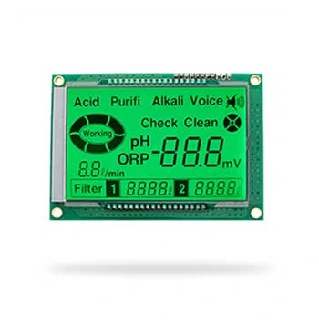
Below is a typical "8" electrode pattern.

The principle is the same for more complex patterns.

The 8 inch displays might be affected and delay for an accident.
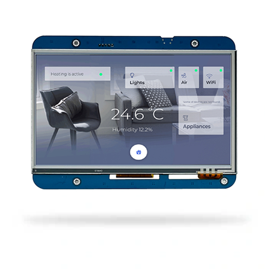
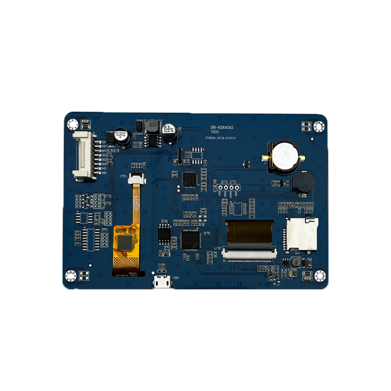
LCM, namely LCD display module and LCD module, refers to the assembly of LCD devices, connectors, peripheral circuits such as control and drive, PCB circuit board, backlight, structural parts, etc. In the home theater, LCD has become the mainstream, bringing joy to more families.
New iPhone 13 Series will use On-Cell OLED Displays. And it that will be launched in the second half of this year will be exclusively supplied by Samsung Display (SDC)
Top 10 LCD Display Manufacturers in China (2026 Guide for OEM Buyers)
Sinocrystal provides a secure and reliable packaging system for LCD displays, ensuring maximum protection against shock, moisture, and static electricity during global transportation.
Discover how LCD displays are evolving in industrial automation — from high-brightness and rugged designs to smart connectivity and energy efficiency. Explore what’s next for industrial-grade visual interfaces.
Discover the key factors to consider when choosing an LCD display for your project, including size, resolution, interface, brightness, and customization options from a factory-direct manufacturer.