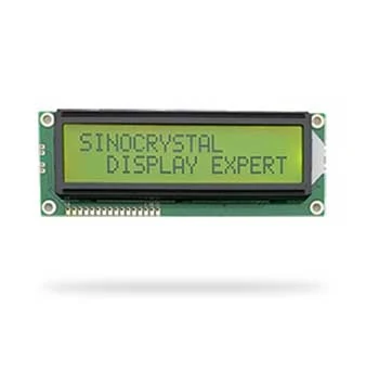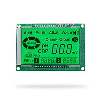
General Specification
| ITEM | STANDARD VALUE | UNIT |
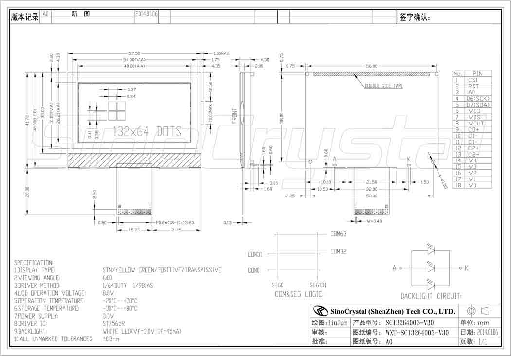
| NUMBER OF GRAPHIC | 132×64 | Mm |
| MODULE DIMENSION | 57.5×41.7×8.1 | Mm |
| VIEWING AREA | 54.0×41.0 | Mm |
| DOT SIZE | 0.34×0.38 | Mm |
| DOT PITCH | 0.37×0.41 | Mm |
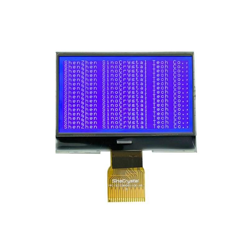
| LCD TYPE | STN/YELLOW-GREEN/POSITIVE/TRANSMISSIVE | |
| DUTY | 1/64 | |
| VIEWING DIRECTION | 0.25 | o’clock |
| BACK LIGHT TYPE | SIDE LIT LED | |
| BACK LIGHT COLOR | WHITE | |
| APPROX. WEIGHT | TBD | G |
Interface Definition
| NO | SYMBOL | LEVEL | FUNCTION |
| 1 | CS1 | H/L | Chip select signal |
| 2 | RST | H/L | Chip reset signal |
| 3 | A0 | H/L | Register selection input H : Indicate that D0 to D7 are display data. L:Indicate that D0 to D7 are control data |
| 4 | D6(SCK) | H/L | D6 : the serial clock input (SCK) |
| 5 | D7(SDA) | H/L | D7 : serial data input (SDA) ; |
| 6 | VDD | 3.3V | Supply voltage for logic |
| 7 | VSS | Ground | Ground |
| 8 | VOUT | — | Power for LCD |
| 9 | C3+ | — | DC/DC voltage converter. Connect a capacitor between this terminal and the CAP1N terminal. |
| 10 | C1- | — | DC/DC voltage converter. Connect a capacitor between this terminal and the CAP1P terminal. |
| 11 | C1+ | — | DC/DC voltage converter. Connect a capacitor between this terminal and the CAP1N terminal. Reset signal. |
| 12 | C2+ | — | DC/DC voltage converter. Connect a capacitor between this terminal and the CAP2N terminal. |
| 13 | C2- | — | DC/DC voltage converter. Connect a capacitor between this terminal and the CAP2P terminal. Chip select. |
| 14-18 | V4-V0 | — | This is a multi-level power supply for the liquid crystal drive. |
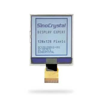
Previous Product Previous Product : 128128 Graphic Display Mono LCD With 2.2INCH COG FSTN ST7571-G4C IC 30 PIN