LCD driver IC is the main part of the display imaging system, integrated resistors, regulators, comparators and power transistors and other components, including LCD modules and display subsystems, is responsible for driving the display and controlling the drive current and other functions, which is divided into two methods: static drive and dynamic drive.

Driver IC features:
Internal self-built 256khzrc oscillator, external 32.768khz crystal or 256khz frequency input, internal 32 × 4bit display. ram optional 1/2 or 1/3 bias, and 1/2, 1/3 or 1/4. end serial interface duty cycle LCD LCD screen built-in lcd driver signal source, internal time reference frequency, available command control operation, buzzer drive Signal frequency selectable 2khz or 4khz. data mode and command mode instructions, with a shutdown instruction can reduce power consumption, r/w address automatically accumulate internal time base generator and wdt. watchdog timer, 3 data storage modes time base or wdt overflow outputs, vlcd pin is used to adjust the operating voltage.

Driver IC:
(1) ram static display: structure of 32×4 bits, storage of the displayed data. ram content is directly mapped to the contents of the driver. ram data can be read, write and read-modify-write command access.
(2) System Oscillator: The cms1621 system clock is used to generate the clock for the time base/wdt circuit, the LCD driver clock and the beep frequency. The clock can come from an on-chip, oscillator (256khz), crystal oscillator (32. 768khz) or an external 256khz clock set by s/w.
(3 Time base and watchdog timer: The time base generator is composed of an 8-stage incremental counter designed to produce an accurate time base. The watchdog timer (wdt) consists of an 8-stage time base generator and a 2-stage incremental counter. It is used to stop the master controller or other subsystems under abnormal conditions (unknown or unwanted jumps, execution errors, etc.).
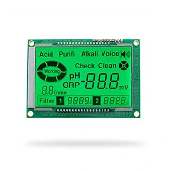
(4) Buzzer output A simple buzzer oscillator is provided in the cms1 621. The buzzer oscillator can provide a pair of buzzer drive signals, bz and bz, which are used to generate a simple buzzer. Two beep frequencies can be generated by executing the tone4k and tone2k commands. The tone4k and tone2k commands set the beep frequency to 4khz and 2khz, respectively, and the beep drive signals can be turned on or off by calling the tone on or tone off commands.
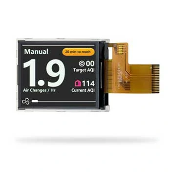
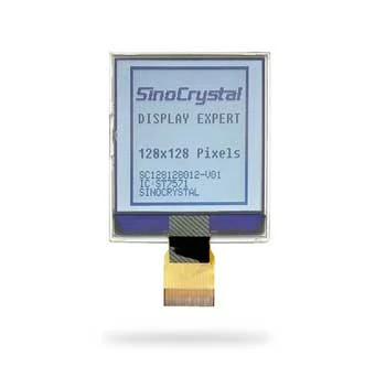
(5)LCD LCD Driver IC cms1621 is a 128(32×4) dot-matrix lcd driver which can drive 1/2 or 1/3 bias, 2, 3 or 4 com end lcd displays, this feature makes the cms1621 suitable for a wide range of lcd displays.
(6) Command Format: cms1621 can be set up by s/w. The commands to set up cms1621 and transmit lcd display data consist of two modes, command mode and data mode. The setting of cms1621 is called command mode, where id is 100, and consists of system setting command, system frequency selection command, lcd structure command beep frequency selection command and operation command.
(7) Interface cms1621 has 4 lines that need to be interfaced. cs initializes the serial interface circuit and connects the communication end in between the main controller and. When cs is 1, data and commands are disabled and initialized between the main controller and cms1621.
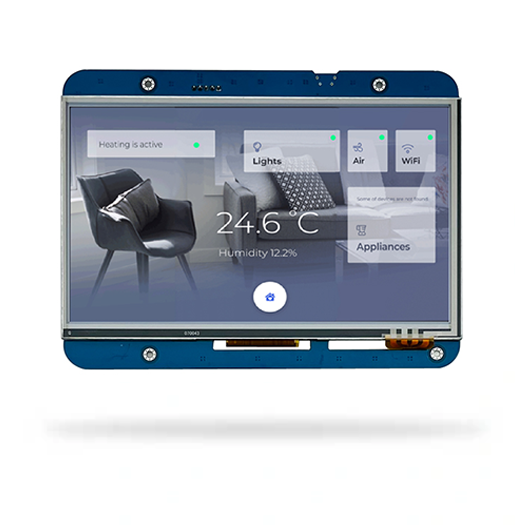
The 8 inch displays might be affected and delay for an accident.
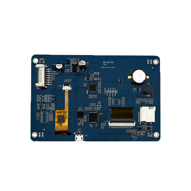
LCM, namely LCD display module and LCD module, refers to the assembly of LCD devices, connectors, peripheral circuits such as control and drive, PCB circuit board, backlight, structural parts, etc. In the home theater, LCD has become the mainstream, bringing joy to more families.
New iPhone 13 Series will use On-Cell OLED Displays. And it that will be launched in the second half of this year will be exclusively supplied by Samsung Display (SDC)
Top 10 LCD Display Manufacturers in China (2026 Guide for OEM Buyers)
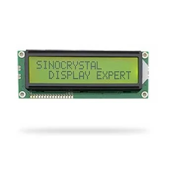
Sinocrystal provides a secure and reliable packaging system for LCD displays, ensuring maximum protection against shock, moisture, and static electricity during global transportation.
Discover how LCD displays are evolving in industrial automation — from high-brightness and rugged designs to smart connectivity and energy efficiency. Explore what’s next for industrial-grade visual interfaces.
Discover the key factors to consider when choosing an LCD display for your project, including size, resolution, interface, brightness, and customization options from a factory-direct manufacturer.